Stave Falls power tunnels - an overbreak assessment
Paul Rapp - BC Hydro, Power Supply Engineering, Burnaby, BC
Bruce Ripley - Ripley Rock Engineering Inc., White Rock, BC
Overbreak measurements were carried out in two power tunnels in order to determine the contribution to total overbreak of drill hole alignment and geology. The power tunnels were excavated at BC Hydro’s Stave Falls plant in 1996/97. The tunnels were driven on parallel alignments separated by a pillar about 12 m wide. Tunnel 1 is 178m long and Tunnel 2 is 198m long. Tunnel grades vary from 0% to 18.9%. Typical tunnel cross section is straight leg horseshoe with width and height of 6.7m. Bedrock at the Stave Falls site is primarily quartz diorite with mafic and siliceous dykes. The tunnels are located beneath the valley wall of the original river channel and have variable rock cover of 15m to 25m. An orthogonal joint set is present at site, consisting of two sub-vertical (J1 and J2) and one sub-horizontal (J3) joint sets. The tunnel alignments were within 20o of the strike of the J1 sub-vertical joint set. Rock conditions are listed below:
The tunnels were driven by full-face drill and blast using a two boom electric-hydraulic jumbo. Perimeter holes in the walls and arch were drilled at 0.6m to 0.9m spacing. Rock support during excavation consisted of spot bolting with 2.4m and 3.6m long resin-grouted rock bolts. Bolting averaged two bolts per meter of tunnel. The tunnels were fully shotcrete lined to reduce hydraulic roughness. The as-built tunnel cross section was influenced by the local geological conditions and often broke back to J3 joints to form a flat roof and to J1 joints in the walls. |
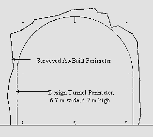
Total overbreak in the walls and arch of the tunnels was determined by comparing surveyed as-built cross sections to the design cross section at 3m intervals along both tunnels. Typical tunnel round length was 3.5m and the 3m survey interval was found to give an unbiased sampling of locations along a tunnel round. This is important since drilling overbreak is greater near the end of a round due to drillhole lookout. The average total overbreak was calculated by dividing the additional area due to overbreak by the design tunnel perimeter. The cross sections and overbreak calculations do not include the tunnel inverts. Drilling overbreak was determined by measuring the distances between the design tunnel perimeter and drill hole traces on the surveyed tunnel cross-sections. This includes drilling overbreak due to planned drill hole lookout and unplanned drill hole alignment errors. Geologic overbreak was calculated as the total overbreak minus the drilling overbreak.
Typical Tunnel Survey Cross-Section Reference: Ripley, B.D, Rapp, P.A., and Morgan, D.R. (1998) Shotcrete design, construction and quality assurance for the Stave Falls tunnels, Canadian Tunnelling Canadienne, Proc. 15th Canadian Tunnelling Conference, Vancouver |
|||||||||||||||


