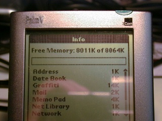
Palm V 8M Upgrade
The Palm V is upgradable to 8M. To successfully do this, there are four main steps:
This is a potentially damaging step. The case is glued shut. Use a hair dryer to melt the case glue a bit and pry it open. Be very careful to avoid heating the screen. Too much heat will damage it. The same applies to the black button assembly. Too much heat and it will dry out and shrink. You'll need to remove both the front and back of the case. The power button will fall out when you remove the front -- don't lose it. Don't remove the exess glue, since it will be used later to reseal the case.
Once open, the parts need to be separated. The battery is also held in place by glue. It can be carefully pried away without heat, and unplugged from the system board. There are two connections from the screen to the system board (one is the digitizer, the other is the LCD display). Unplug these (don't force it. There is a locking mechanism on each cable. The button assembly is held in place on two plastic posts. Roger Dewsbury's page (link above) has a bit more detailed information about the case and getting it all apart.
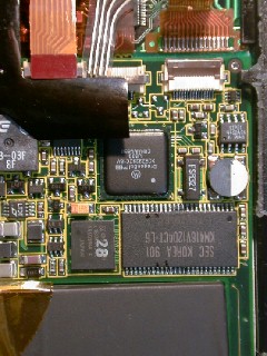
Removing the 2M Dram chipThe Dram chip is the rectangular chip at the bottom right in this picture:
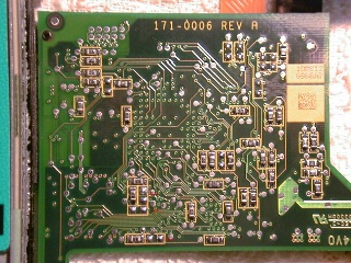
Once Install the replacement chip in the same orientation as the 2M chip was. Compatible part numbers are at the bottom of this page.
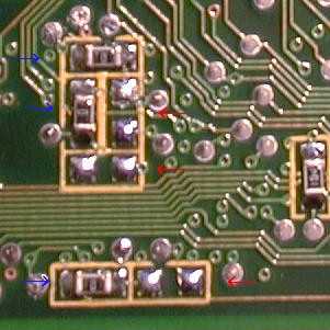
Moving the resistorsOn the other side of the board, is a bunch of traces and resistors:
Carefully reassemble everything. Before you put the case on, you can hook up the display, system board and battery, and see if your work was successful. If you do this, be careful not to accidentally short out anything. Once you know its working, seal the case with heat, and hold some pressure on it while the glue dries (about 5 minutes).